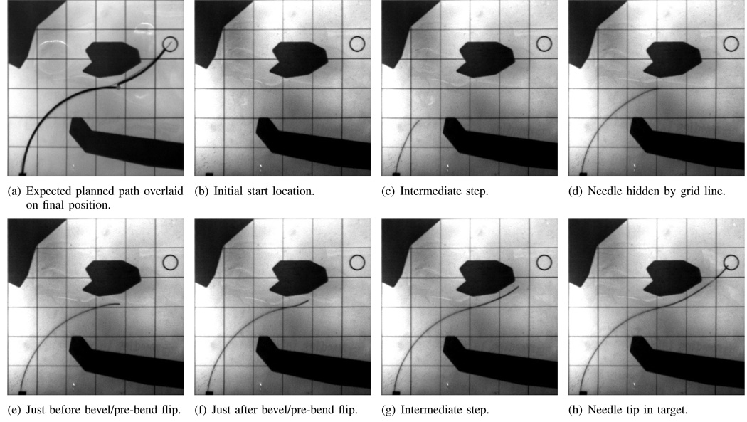
Fig. 4.
Path A: Needle path when the needle enters at the expected location (1 cm,0 cm). Images are taken from the cameras during the experiments. Each square is 2 cm on each side. The grid lines and obstacles are printed on transparency film and are overlaid on top of the phantom tissue during the experiments.

