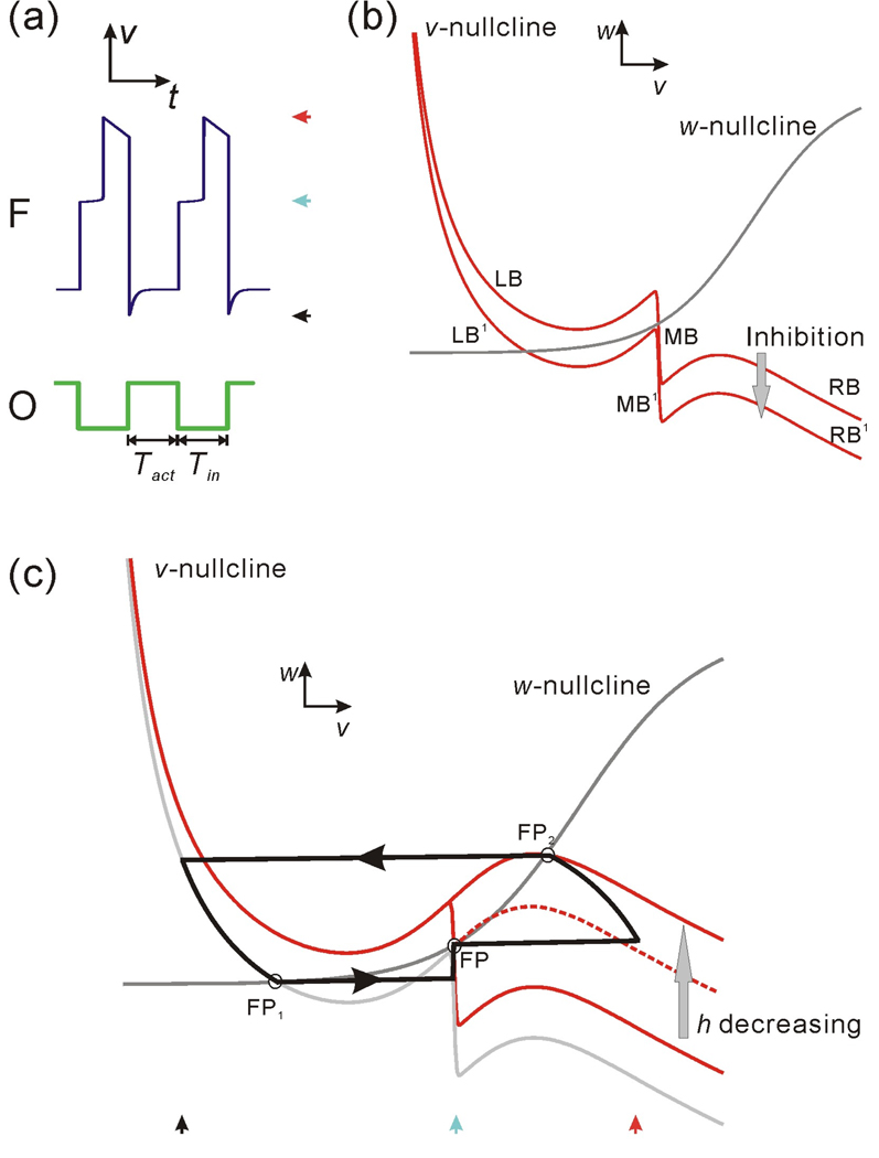
Figure 2.
The oscillation cycle of the model follower neuron F shown in the membrane potential trace and in the v-w phase plane. (a) The membrane potentials of F and the oscillator O (modeled as a simple square wave). Tact and Tin represent the active and inactive durations of O. (b) The nullclines in the v-w phase plane. LB, MB and RB respectively represent the left, middle and right branch of the v-nullcline without inhibition, while LB1, MB1 and RB1 represent the same three branches under inhibition. (c) The trajectory of F in the v-w phase plane. During the inhibition (Tact), the trajectory moves along LB1 to FP1. Following the inhibition, it jumps to MB and moves toward FP on MB; at the same time MB shrinks from its lower knee as h decreases. The trajectory stays at FP until the lower knee encounters FP and allows it to jump to RB (which is moving up as h decreases). The trajectory moves on RB until it reaches FP2. It then stays at FP2 until the next cycle of inhibition at the onset of the O activity. The three red curves represent the v-nullclines for different values of h with the solid curves corresponding to the minimum and maximum h values.

