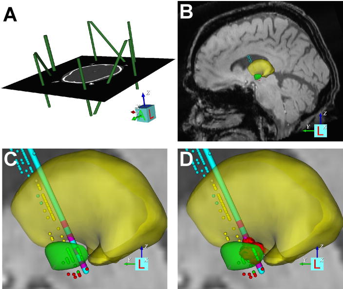
Figure 1.
Patient-specific DBS model. (A) The CRW stereotactic coordinate system (green imaging fiducials within the context of the pre-operative CT) was defined relative to the imaging data. (B) Microelectrode recording data were entered into the model (thalamic cells, yellow dots; subthalamic cells, green dots; substantia nigra cells, red dots), and a 3D brain atlas was fitted to both the neuroanatomy and neurophysiology (yellow volume, thalamus; green volume, subthalamic nucleus). (C) The implanted DBS electrode location was defined in the model. (D) The VTA (red volume) for each clinically evaluated stimulation parameter settings was calculated.

