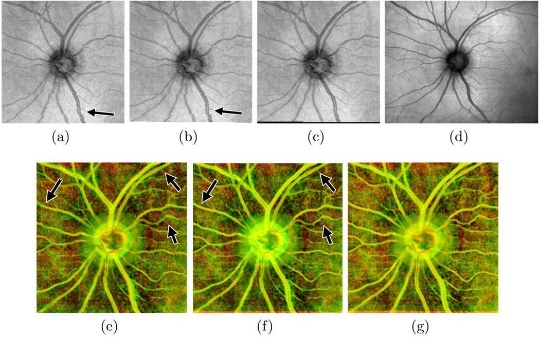
Fig. 1.
Results of motion artifact correction on an example scan. The en face image from the uncorrected scan (a) shows vessel discontinuities (arrow) resulting from microsaccades. Correcting for tremor and drift (b) fails to correct these discontinuities, but microsaccade correction does (c), matching the SLO reference image (d). Images (e)–(g) show the en face image in the red channel and the SLO image in the green channel before correction, after correcting tremor and drift, and after full correction, respectively. Correctly aligned regions appear yellow; arrows point to improved alignment after drift correction.

