Figure 2.
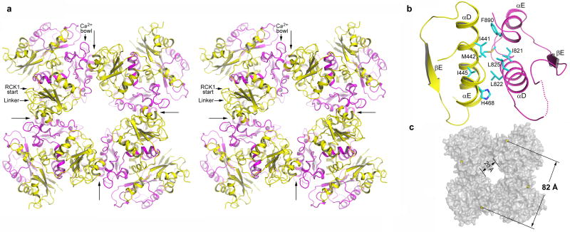
Four BK intracellular subunits assemble into a gating ring. a, Stereo diagram of the gating ring structure viewed down the 4-fold axis from the extracellular side. Four long arrows indicate the position of inter-subunit assembly interfaces and define the boundary of each subunit. RCK1 and RCK2 in each subunit are colored yellow and magenta, respectively. The linker between RCK1 and the channel pore, the starting point of RCK1, and the position of the Ca2+ bowl are labeled on one subunit (upper left corner). b, An enlarged view of the assembly interface formed by helices αD and αE from both RCK1 (yellow) and RCK2 (magenta). The side chains of those hydrophobic residues important for protein-protein contacts are also shown. The disordered loop between αD and βE is drawn as a dotted line. c, Overall shape of the BK gating ring in surface representation. Yellow spheres represent the Cα atoms from Arg342s used to define the diagonal length of the gating ring.

