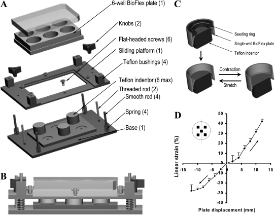
Figure 1.
Description and validation of the stretch–contraction device. (A) Assembly of the stretch–contraction device. Teflon indentor posts are positioned beneath each well to be strained. In the configuration shown here, three wells (out of a total of six wells) are left unstretched for control measurement (quantity in parentheses). (B) Side view of the stretch–contraction device assembled with a BioFlex plate. (C) Single-well cross sections describing contraction and stretch. (D) Changes in linear strain relative to plate displacement assessed by measuring with video microscopy the relative deformation of markers (inset) drawn on the flexible silicon membrane.

