
Fig. 5.
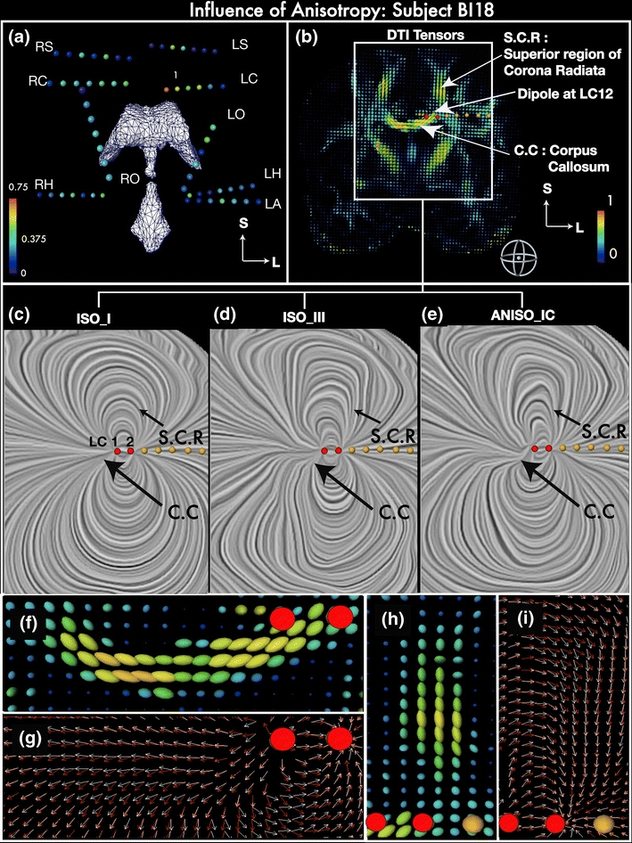
Influence of anisotropy on the intracranial current flow. (a) Coronal view of implanted depth electrode contacts in subject BI18 as spheres colored coded with the Fractional Anisotropy (FA) at the contact location. The spheres are rendered along with the ventricles (in white) to assist visualization of their approximate spatial locations. The deepest contact of the LA electrode is in or near the Left Amygdala, LH: Left Hippocampus, LS: Left Supplementary Motor, LC: Left Cingulate, LO: Left Orbito-frontal, RH: Right Hippocampus, RO: Right Orbito-frontal, RS: Right Supplementary Motor, RC: Right Cingulate. (b) DTI tensors in a coronal plane containing electrode LC in subject BI18, visualized as 3D ellipsoids color coded with FA values; the Corpus Callosum (C.C) and Superior region of corona radiata (S.C.R) are labeled. (c, d, e): Current density vectors in the region inside the white rectangular box in (B) are visualized using the LIC (Linear integral convolution) technique for a dipole at LC12 in model types ISO_I, ISO_III and ANISO_IC, respectively. The direction of the current is indicated by the texture. (f, h) 3-D renderings of diffusion tensor ellipsoids near stimulation site LC12 in C.C. and S.C.R., respectively. (g, i) Electric current density (ECD) vector near stimulation site LC12 in C.C. and S.C.R., respectively. White arrows indicate the current flow in the anisotropic white matter model ANISO_IC whereas red arrows indicate the direction of the current in the isotropic model ISO_III. Red dots in panels B-I indicate contacts LC1 and LC2. Another example is shown in Supplementary Figure 3 (dipole RC12 in subject BI15)