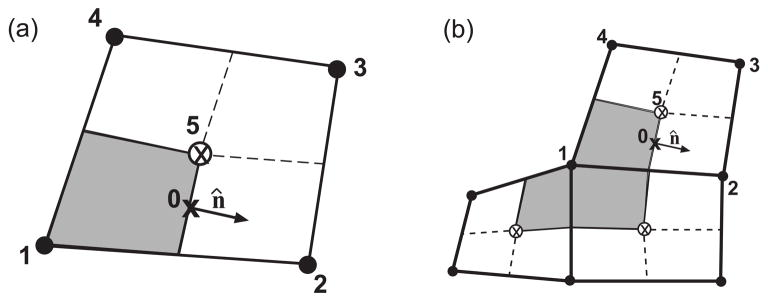
Fig. 2.
(a). A distorted quadrilateral area defined by the nodes labeled 1 – 4. The center of the quad is denoted by ⊗ and is labeled as location 5. We focus our attention on the node labeled 1. The subcontrol volume about this point, Δv1, is shaded in grey. The text describes computation of the flux through the eastern side of the area, which is centered about the point labeled 0. The normal vector along this side is n̂. (b). Schematic showing the full control volume about node 1, ΔV1 (shaded in grey), which is subdivided into three subcontrol volumes. (Note that here node 1 is a boundary node. Interior nodes have four control volumes.) To compute the total number of particles entering the control volume of node 1 in a unit time, we integrate the flux over the boundary of ΔV1. Volume integration is achieved by integrating over each subcontrol volume and then summing.

