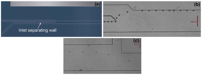
Fig. 3.
a Conceptual rendering of the bead injection region. The wall between the two inlets ensures that the beads always enter the main channel from the same point. b Composite micrograph of a bead entering the main channel and being pulled against the sidewall in the antigen stream. c Composite micrograph of a bead transferring from incubation stage 1 to stage 2

