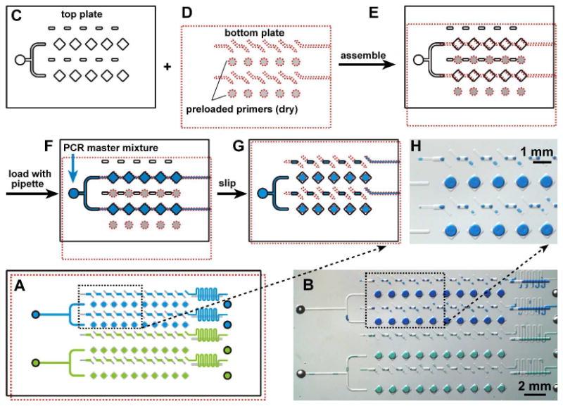
Figure 1.

Assembly and operation of the preloaded multiplex PCR SlipChip. A) Schematic drawing shows the PCR SlipChip after introducing two different samples (blue and green) and slipping to combine the sample with the preloaded primers. B) A bright field image of the experiment described in A) using food dyes instead of the samples. C) The top plate of the PCR SlipChip contained square wells, rectangular wells, sample inlets, and outlets (outlets not shown) and D) the bottom plate of the PCR SlipChip contained ducts for the samples and preloaded circular wells with different PCR primers. E) The SlipChip was assembled and the two plates were aligned such that the sample wells and sample ducts lined up to form a continuous fluidic path. F) The sample, the PCR master mixture, was flowed through the fluidic path to load the sample wells. G) The PCR SlipChip was slipped to align the square sample wells with the circular primer wells. When the PCR mixture touched the primer on the bottom of the primer well, the PCR primer dissolved in and mixed with the reaction mixture. After the SlipChip was slipped, thermal cycling was performed. H) Microphotograph shows the formation of droplets within the wells after the aqueous dye (representing the PCR mixture) was slipped to contact wells containing oil.
