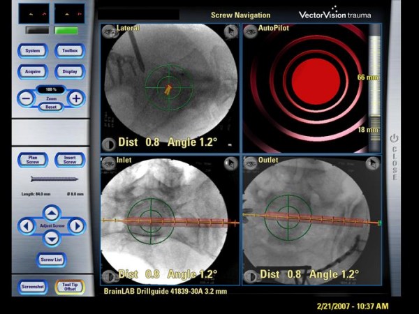
Figure 1.

Sterile covered touch screen of the navigation system (Vector Vision, Brainlab). displaying the standard images (lateral view, inlet, outlet) and an auto-pilot view. Red bar: virtually planned SI-screw; yellow line: prospective path of the navigated guide wire (trajectory), green bulls-eye: reflecting the exact positioning of navigated instruments to achieve the planned screw position.
