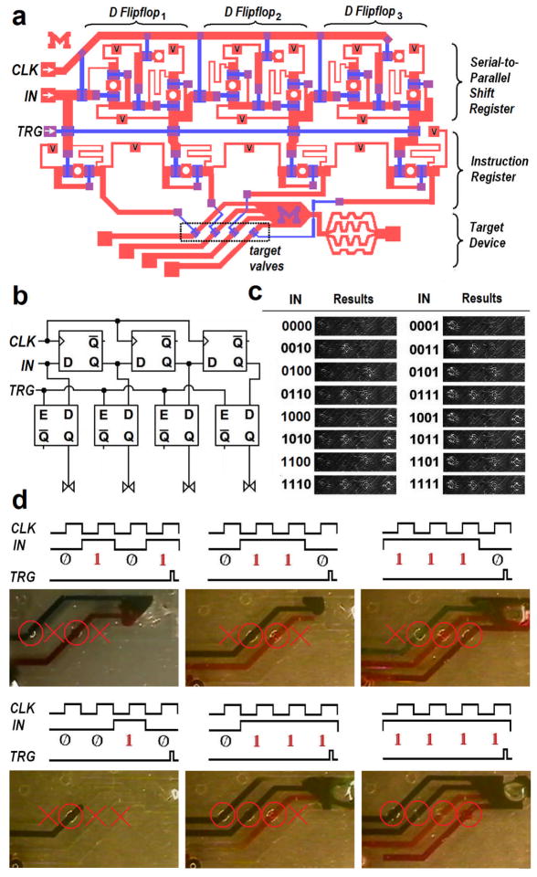
Figure 10.
4-bit digital pneumatic microprocessor. (a) CAD design of the 4-bit processor consisting of a 3-bit MSR with three D flip-flops and a 4-bit instruction register that controls the target mixing device with four independent valves. Serially encoded input commands are shifted by accompanying clock pulses, generating four independent parallel outputs to control the corresponding command valves in the fluidic channels. (b) Electrical symbolic representation. (c) Statuses of four target command valves depending on the input commands. (d) Various command sequences were supplied to perform different mixing tasks. Note that the maintained outputs keep some valves open and the others closed during mixing operations.

