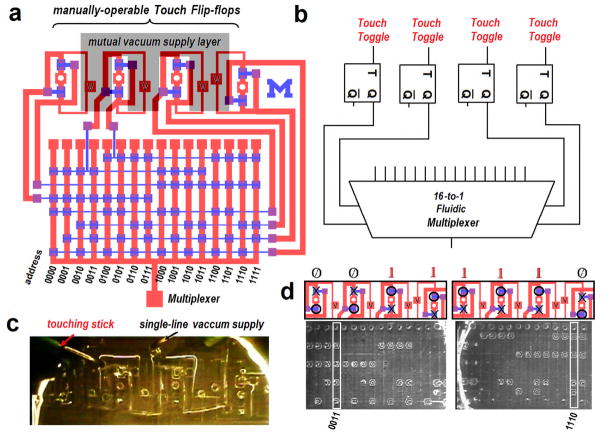
Figure 13.
Touch Microfluidic Control. (a) CAD design of a manually operable multiplexer by four ‘touch’ flip-flops that generates independent outputs to address sixteen channels by multiplexing. For the entire platform, vacuum must be supplied to four different ports. Black dashed boundaries indicate the third ‘supply’ layer where vacuum is distributed from one line to all ports simultaneously without separate tubing. (b) Electrical symbolic representation. (c) Photo of the PDMS ‘supply’ layer on the top of the device. The vacuum supply layer covers all of the four vacuum ports (‘V’s) and a single line of vacuum is supplied to the layer in order to power up the entire device. (d) Various addresses can be accessed by touching one or more valves in the touch flip-flops. Fluid samples can flow along the channel with all of its four valves open.

