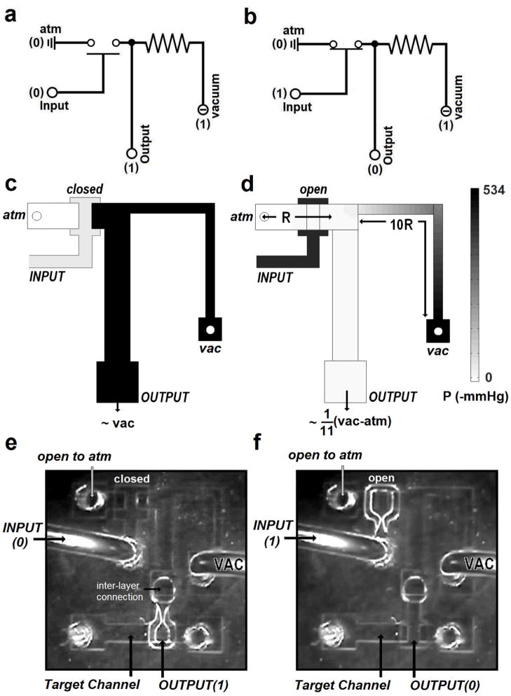
Figure 2.
Electrical representations of the pneumatic inverter, NOT gate, are shown: (a) when the valve is closed (switch open), the main channel becomes discontinued, making vacuum-side channel a closed system. Vacuum will be transferred to the output without pressure drop. (b) when the valve is open (switch closed), the main channel becomes connected, generating pressure drop along the channel. Since most of the resistance exists at the vacuum-side, the output becomes close to atmospheric pressure. Schematics and simulated pressures in a NOT gate are shown for input signals of atmospheric pressure (c) and vacuum (d). The channel connecting the vacuum source to the output has ~10 times more flow resistance than the channel connecting the pressure source. The right panel (d) explicitly shows the pressure gradients due to this resistance, producing almost atmospheric pressure as the output. Visual observations with the asymmetric NOT gate operating on the inputs of atmosphere (e) and vacuum (f). When the input valve is closed (input signal of atmospheric pressure), the output channel goes to vacuum. When the input signal is vacuum, the input valve open and the output pressure increases to near atmosphere.

