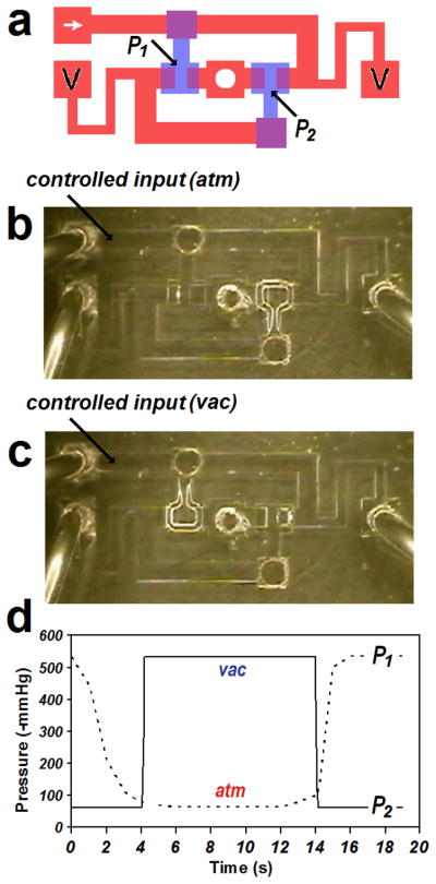
Figure 7.
Operation of a pneumatic bistable flip-flop. (a) CAD design of a flip-flop. The pressure levels of P1 and P2 are indicators for the flip-flop’s states. (b) When input at P1 of 0 is forcedly supplied, the input-side valve closes and the other valve instantly opens. (c) When the input of 1 is forcedly supplied, the input-side (left) valve opens and the other (right) valve instantly closes. (d) Plot of pressure level changes. P1 (control) and P2 (response) are always opposite to each other and change only by external perturbations. When the controlled pressure level (P1) exceeds thresholds for the valve, instantaneous pressure changes in response (P2) are observed.

