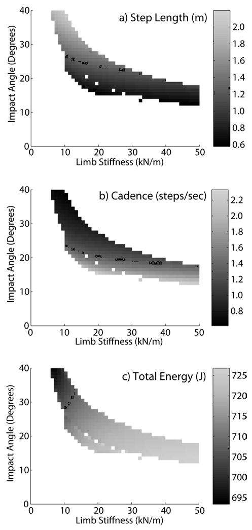
Figure 5.

Shown are the limb stiffness and impact angles that resulted in limit cycle solutions when the 0.3 m roller radius model walked with an average velocity of 1.35 m/s. Each solution exhibits a specific step length (a), cadence (b) and total energy (c). The highest energy states were associated with high cadence-low step length solutions, achieved via coupling high limb stiffness with small impact angles.
