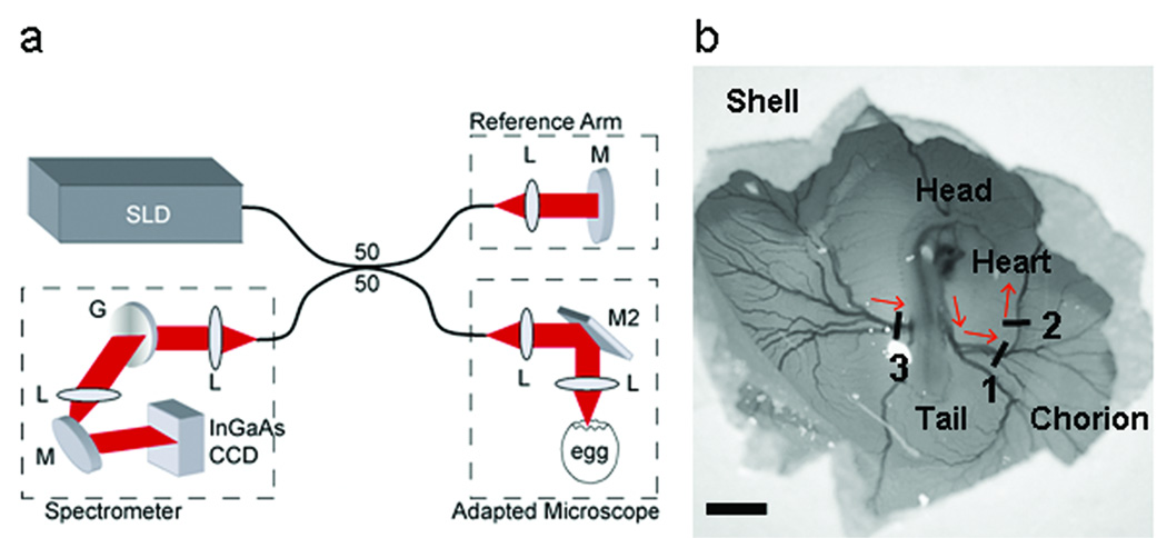
Figure 1.
Spectral domain optical coherence tomography (SDOCT) microscope system. (a) SDOCT system setup. A low-coherence light source (λ=1310 nm) was used in a fiber based Michelson interferometer design where the optical power was split using a 50/50 coupler into reference and sample arms. The interferogram was measured using a custom-made spectrometer containing a 512 element InGaAs CCD detector (Sensors Unlimited). (b) Scanning of the SDOCT beam across three vessels was performed using an adapted Zeiss stereo zoom microscope. Red arrows indicate direction of blood flow. SLD, superluminescent diode (InPhenix); L, lens; M, mirror; M2, dual-axis scanning mirror (Optics in Motion); G, grating (Wasatch). Scale bar = 5 mm.

