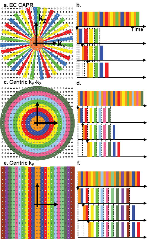
Figure 2.

Illustration of kY-kZ sampling patterns and temporal ordering for view orders. (a,b) EC CAPR. Sampling consists of a central circular region (orange) and a peripheral region apportioned into N vane sets. Here N is set to 4. (c,d) Centric kY-kZ. k-space is apportioned into a central circle (orange) and N concentric annuli. (e,f) Centric kY. k-space is apportioned into a central rectangle (orange) and N rectangles centered about the kY axis. For each view order the center and one section of the periphery are acquired each image update (b,d,f).
