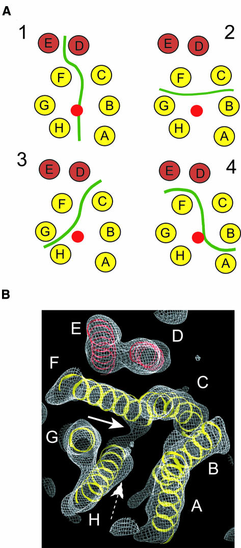
Fig. 5. Possible arrangements of monomers in the dimer. (A) Four possible monomer boundaries in the EmrE dimer are shown. The transmembrane helices are depicted as circles distributed as in the central section of the structure shown in Figure 3C. A red circle depicts the location of the substrate TPP+. A continuous green line illustrates the hypothetical interface between monomers. (B) View of the density map contoured at 1.0 σ to show the connection of density between helix H and helix F (white arrow). The density for TPP+ is also shown for reference (dashed arrow). The view is along helix G and from the same side as in Figure 2.

An official website of the United States government
Here's how you know
Official websites use .gov
A
.gov website belongs to an official
government organization in the United States.
Secure .gov websites use HTTPS
A lock (
) or https:// means you've safely
connected to the .gov website. Share sensitive
information only on official, secure websites.
