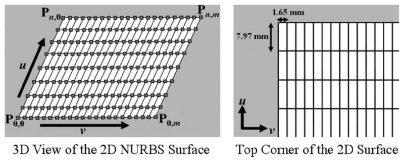
Fig. 5.

2D NURBS surface developed to follow the tag lines of the image planes. The knots (solid lines) of the surface were setup to form a 2D grid. Knot lines running in the v direction were spaced with the tag spacing of the images which was 7.97 mm. The knot lines running in the u direction were spaced more frequently at 1.65 mm for increased sampling. For our work, the 2D NURBS surface was defined with n = 23 and m = 103. The control points and grid points (squares) of the initial surface are located at the intersection of the knot lines.
