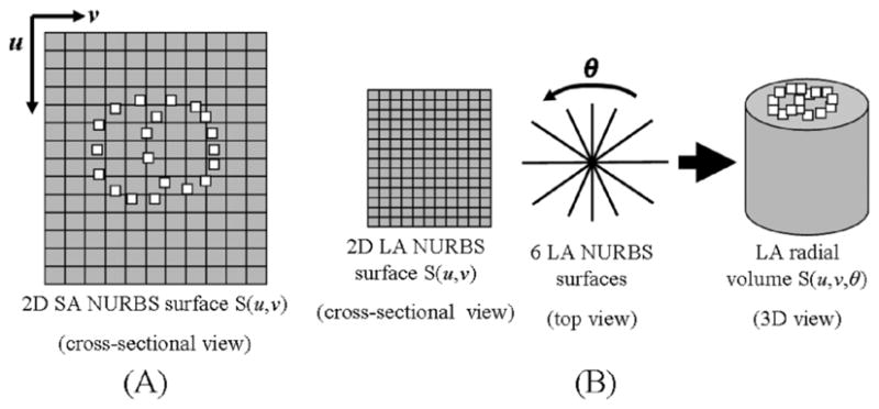
Fig. 9.

(A) Points defining the structures of the RV and LV were defined in surface coordinates (u, v) on the 2D NURBS surfaces for the SA image on which the points were sampled. The NURBS surface fields for the SA images are used to follow the x- and y-deformation of the points for subsequent time frames. (B) The six 2D NURBS surface fields for the LA images at end-diastole were splined about the radial direction θ to form a radial volume. The points defined for the LV and RV were located in volume coordinates (u, v, θ) of the radial volume at end-diastole. Image volumes were similarly created for subsequent time frames, and the volume coordinates were used to track the z-deformation of the points.
