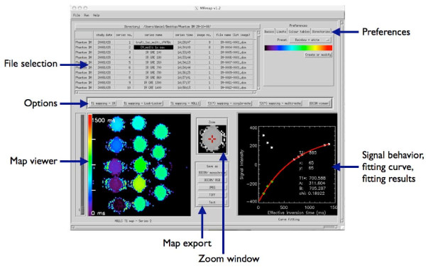
Figure 1.

Main screen of MRmap (screenshot with MOLLI T1 map of a gel phantom with multiple T1 times as used for assessment of software accuracy and performance). Elements of the graphical user interface are arranged such that workflow proceeds from top to bottom of the screen (selection of files and preferences - selection of mapping technique - output and export of results). Completed maps are presented in the map viewer. By mouse-clicking onto a pixel of interest, the surrounding region is magnified in the zoom window, and the fitting curve and fitting results of the pixel are displayed on the lower right. On this graph, signal intensities of the raw images are represented by white stars, while reconstructed (negative-signed) real data are given by green diamonds.
