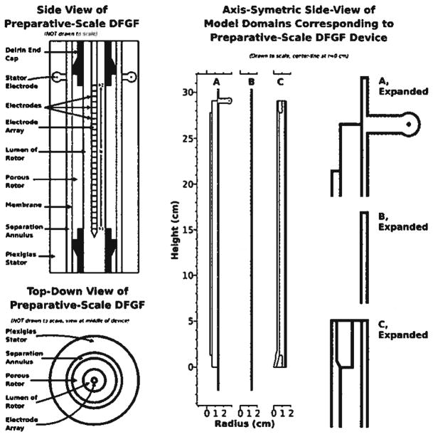
Figure 2.
The two left-most drawings show side and top-down views of the vortex-stabilized electrophoresis chamber modified to perform DFGF. The electrode array fits in the rotor’s lumen. Cooling buffer flows over the electrode array and the electrode located in the stator. A membrane coats the surface of the porous ceramic rotor to keep proteins in the separation annulus. A dialysis membrane segregates the separation annulus from the buffer flowing over the stator electrode. The model domains, in the center and expanded on the right of the figure, represent portions of the device shown on the left of the figure. Domain A is used for calculating the electric potential. Protein transport is solved in the simple rectangular domain B, which represents the separation annulus. Domain C covers the parts of the system relevant to heat transfer.

