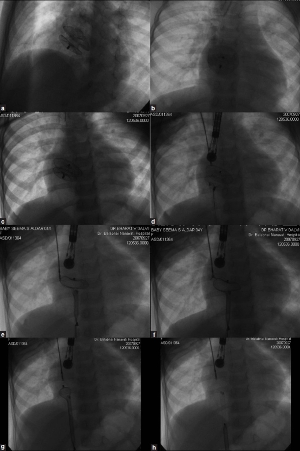
Figure 2.

Fluroscopic images immediately after deployment, showing the normal position of the device (a) in left anterior oblique projection with cranial angulation and (b) posteroanterior projection. Fluroscopic image 24 hours later showing (c) migrated device (d) held by a bioptome from the right jugular vein and a snare from the right femoral vein (e) Right atrial disk being pulled into the 10F sheath, with left atrial disk still held by the bioptome. (f) Bioptome is opened to release the left atrial disk. (g) The left atrial disk being pulled into the sheath. (h) The entire device is slenderized and brought into the sheath
