
Figure 2.
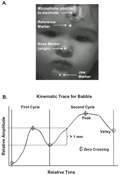
Panel A illustrates placement of kinematic markers and microphone on the participant. Panel B illustrates the location of zero crossings in the displacement trace and how these landmarks defined the peak(s) and valley(s) in the displacement trace. Panel B also illustrates that vertical changes in jaw height had to be greater than 1 mm.