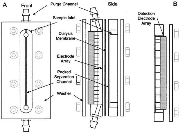
Figure 2.
DFGF schematic. (A) The purge channel circulates cooling buffer to remove Joule heat and electrolysis products. The separation channel is packed with a chromatographic resin to reduce band dispersion due to mass transfer effects and convection. The dialysis membrane separates the purge channel from the separation channel. The membrane allows the passage of current carrying ions but does not allow the passage of higher molecular weight species. The 21-pin electrode array is connected to the controller via a SCSI ribbon cable. (B) Front block used for measurement of voltage profile in separation channel. This block contains 11 platinum electrodes spaced at a 0.508 cm pitch. Measurements of each electrode are made relative to ground.

