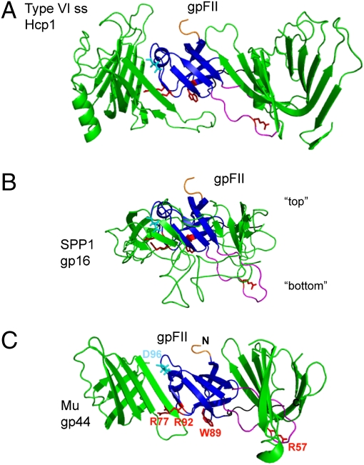
Fig. 3.
Models of the arrangement of gpFII within phage particles. Models were made by structurally aligning gpFII to (A) Hcp1 in the hexameric form found in its crystal structure (PDB accession no. 1Y12), (B) the head–tail joining protein of phage SPP1 (gp16) as it was modeled into cryoEM density of the whole connector of SPP1, and (C) the phage Mu baseplate hub (gp44) pseudohexameric ring (PDB accession no. 1WRU). The view shown is of the β-strands that line the inside of these ring-like structures. In each view, gpFII was overlaid with the center monomer, which is not seen, and two flanking monomers are shown. The other half of each ring is not shown. Residues discussed in this work are highlighted on each model as follows: N terminus (truncated) in orange, β3–β4 unstructured region in magenta, C-terminal unstructured region in black, Asp96 in cyan (a reference point for orientation), and Arg57, Arg77, Trp89, and Arg92 in red. In B, “top” refers to the surface of this connector protein that binds to the head and “bottom” to the surface that binds tails.

