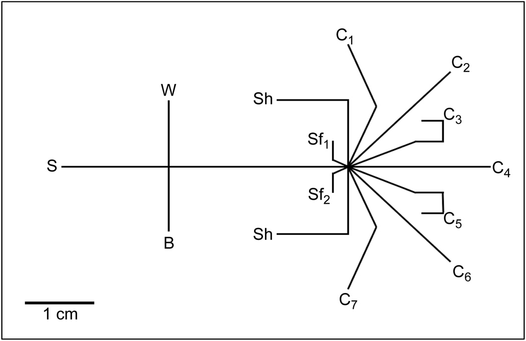
Figure 1. Schematic of the microfluidic device.
Sample (S) was introduced to the separation channel by a gated injection at the intersection of S, buffer (B) and waste (W) channels. Sheath flow channels (Sf1, Sf2) focused separation channel effluent to one of seven fraction collection channels (C1–C7). Flow shaping channels (Sh) were employed to maintain focusing when sample was directed to C1 or C7.

