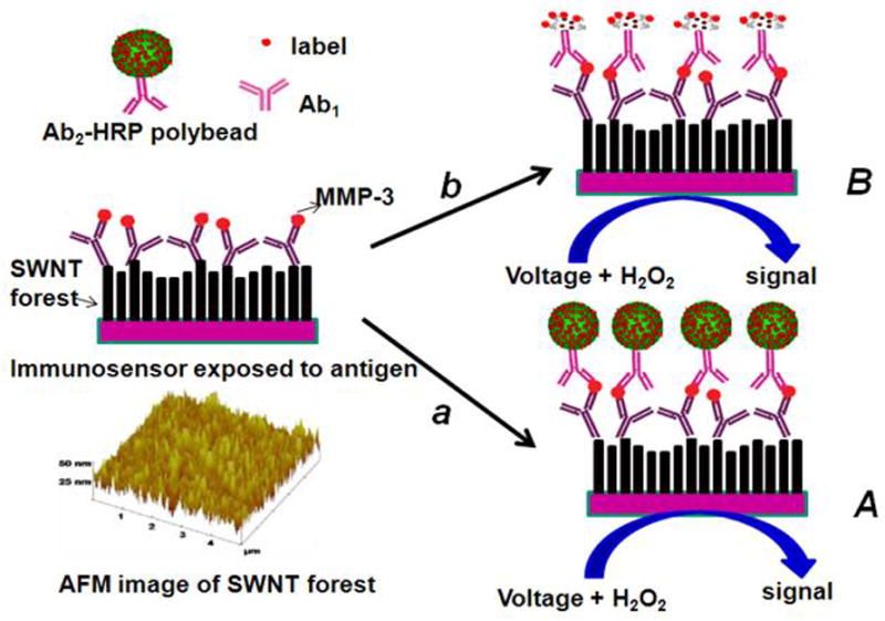
Scheme 1.

Illustration of detection principles of SWCNT immunosensors. On the bottom left is a tapping mode atomic force microscope image of a SWCNT forest that serves as the immunosensor platform. On the right is a cartoon of a SWCNT immunosensor platform used for capture antibody (Ab1) bioconjugation and subsequent antibody–antigen sandwich immunoassay (HRP is the enzyme label). Picture (A) on the right shows the immunosensor after treating with Ab2–Polybead–HRP to obtain amplification by providing numerous enzyme labels per binding event. Picture (B) on the right shows the immunosensor after treating with a conventional HRP–Ab2 (biotinylated Ab2 followed by streptavidin modified HRP) providing 14–16 labels per binding event. The final detection step involves immersing the immunosensor after secondary antibody attachment into a buffer containing mediator in an electrochemical cell, applying voltage, and injecting a small amount of hydrogen peroxide.
