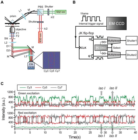
Figure 4. Conformational dynamics of the triply-labeled Holliday junction observed in the TIRF setup.
(a) A schematic diagram of ALEX three-color FRET setup in TIRF microscopy. Then setup was built based on an inverted microscope (IX71, Olympus). For switching purposes, mechanical shutters (LS-3, Uniblitz, Rochester, NY) were used. The fluorescence signals of the three dyes were collected by a water-immersion objective (UPlanSApo 60×, Olympus) and focused on different areas of an electron-multiflier charge coupled device (EM-CCD, iXon+ DU897BV, Andor Technology, Belfast, UK). The identities of other optics are: F1, notch filter (NF03-633E-25, Semrock, Rochester, NY); F2, long-pass filter (LP03-532RU-25, Semrock); D1, dichroic mirror (635dcxr, Chroma); D2, dichroic mirror (740dcxr, Chroma); L1, lens (LA1986-A, Thorlabs); L2, lens (LAO-120.0-40.0/066, CVI); L3, lens (LAO-260.1-50.0/066, CVI); M, mirror (BB01-E02, Thorlabs). (b) A circuit diagram for synchronization of laser switching and image acquisition. The internal trigger line of the EM-CCD is connected to the clock line of a JK flip-flop (74LS112, Motorola, Schaumburg, IL), and the JK flip-flop generates two complementary pulse trains, Q and Q′, which are used to alternately switch two excitation lasers synchronously. A multiplexer is used to select either a data acquisition board (DAQ PCI-6503, NI) or EM-CCD as a source of shutter control signal. (c) Fluorescence intensity time traces of the Holliday junction observed in TIRF microscope with 50-ms bin time. Experiments were performed at room temperature in 10 mM Tris-HCl (pH 8.0) with 200 mM Mg2+.

