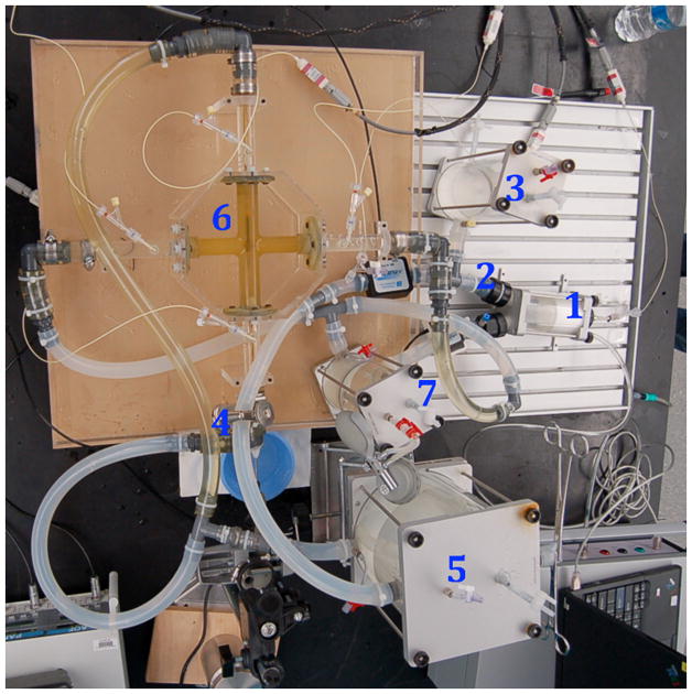
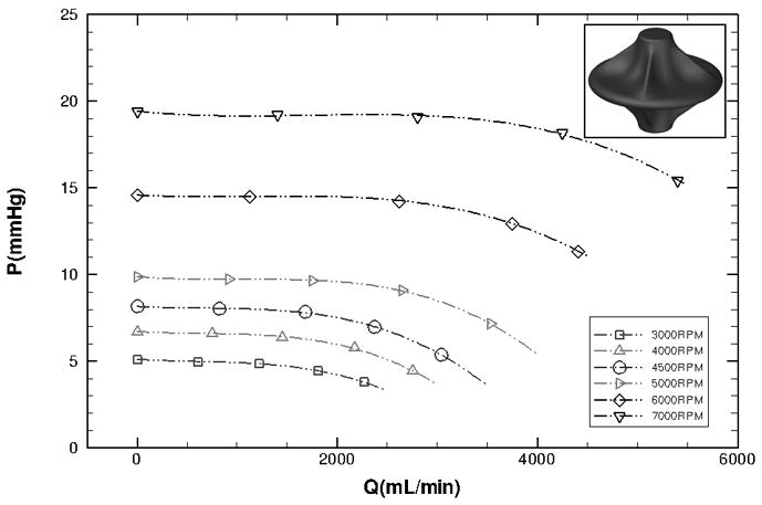
Figure 4.


Prototype hydraulic performance. Left: In vitro mock circulatory loop consisting of the following elements: 1) single ventricle, 2) aorta, 3) arterial compliance, 4) systemic vascular resistance, 5) venous compliance, 6) Fontan junction with viscous impeller pump, 7) pulmonary compliance. Right: Experimental hydraulic performance for a vaned impeller with cage present (P, pressure mmHg; Q, flow mL/min).
