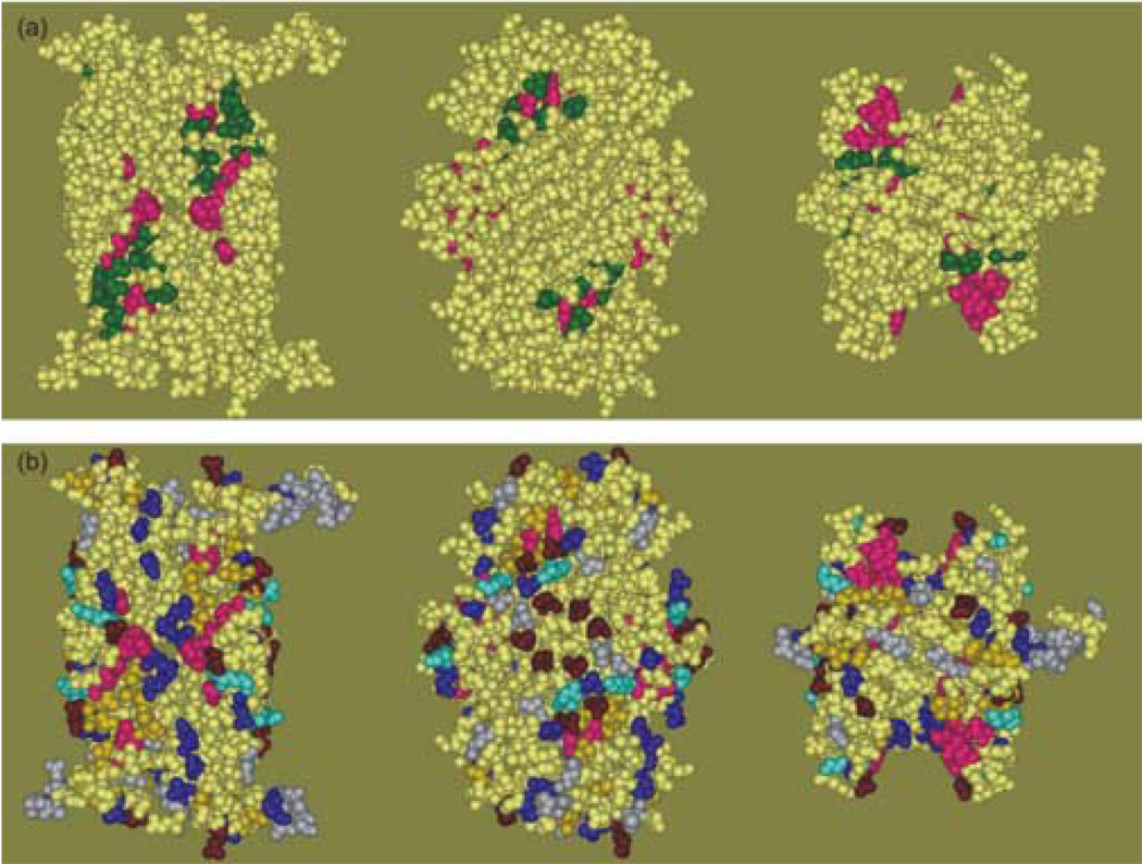
Figure 9.
Panel (a) Binding site previously proposed based on the crystal structure. The structure on the left is a view of the dimer interface. The view in the center was achieved by a 90° rotation about the vertical axis to show the flat -sheet on the side of the tetramer. The view on the right is related to that on the left by a 90° rotation about the horizontal axis toward the viewer. Panel (b) Contact sites identified in this study colored to indicate the nature of the residue. The color scheme is described in the text. The orientation of the structure is as described in panel (a).

