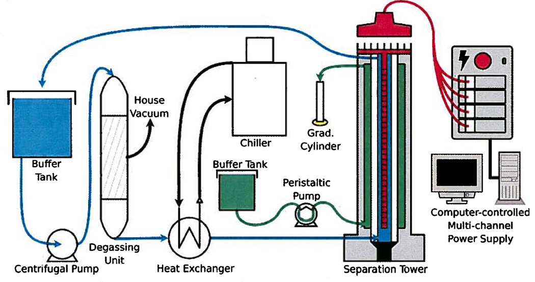
Figure 2.
Computer-controlled, multichannel power supply that established and maintained the electric field gradient on the 32 electrodes mounted to the electrode array in the center of the rotor. The electrical current passed through the rotor and made an electric field gradient in the separation annulus. A centrifugal pump circulated cooling buffer through a degassing unit, a heat exchanger, and then through the rotor’s lumen so that the buffer could cool the separation chamber and purge electrolysis gases produced on the electrode array. A small peristaltic pump generated the counter-flow in the separation annulus.

