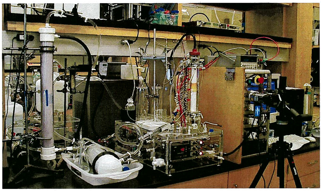
Figure 6.
The preparative-scale DFGF apparatus corresponding to Figure 2. The 20-L cooling buffer reservoir can be seen on the left edge of the photograph. The hollow-fiber degassing module is vertically mounted on a ring stand in the left fore-ground. The heat exchanger is in a plastic tub to the right of the hollow-fiber module and the large gray chiller can be seen behind the heat exchanger. In the center is the clear, acrylic base and separation tower of the preparative-scale DFGF instrument. The cap on the separation tower connected the electrode array in the rotor’s lumen to the multichannel power supply seen on the right of the preparative-scale DFGF instrument. The Spellman power supply is on the shelf above the multichannel power supply. Directly behind the hollow-fiber module is a 10 L reservoir for the purge buffer that flows through the stator electrode housings. A video camera in the right fore-ground recorded the position of the protein over time.

