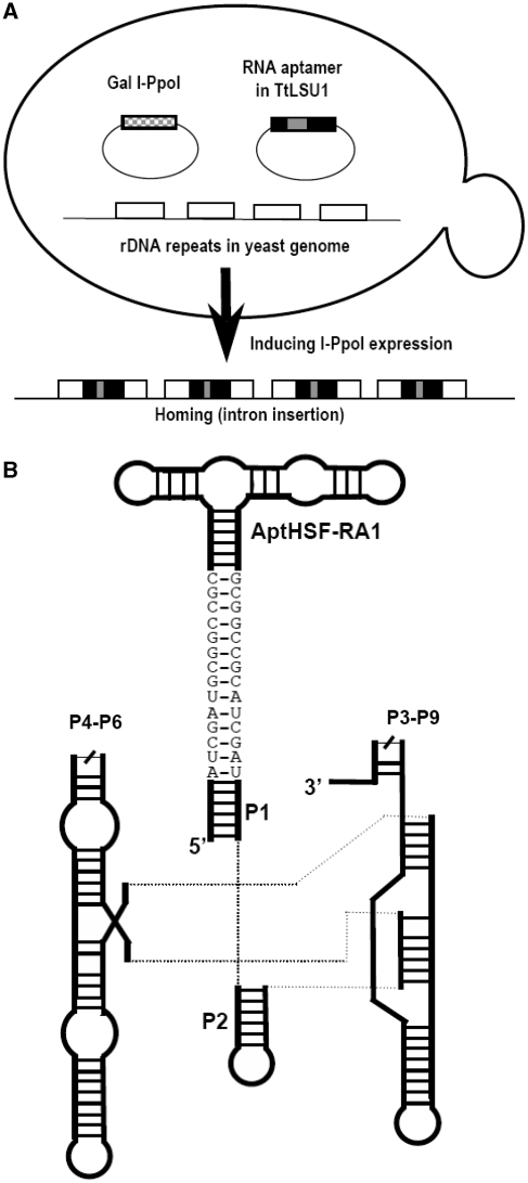
Figure 1.
The indirect aptamer delivery system. (A) Trans-integration of a group I intron. The three components, the host and the two plasmids, are depicted. The arrow shows the transition of rDNA to the intron-homed state caused by I-PpoI cleavage of the rDNA and insertion of the intron-aptamer. (B) Schematic diagram of the intron-aptamer. P4–P6 and P3–P9 signify the two catalytic domains of the group I intron. The sequences shown as bases depict the ClaI sites and the GC clamp extending from the P1 stem.

