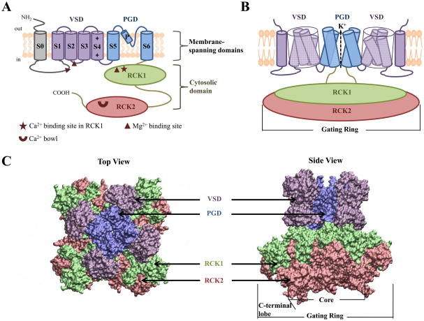
Figure 1.
BK channel structure. A) Membrane topology of the Slo1 subunit of BK channels, which highlights the S0 segment, voltage sensing domain (VSD; S1-S4 segments), pore-gate domain (PGD; S5, P and S6 segments) and cytosolic domain (RCK1 and RCK2). The positively charged residues in S4, and the Ca2+ and Mg2+ binding sites are indicated. B) Cartoon of a functional BK channel where two opposing subunits are shown for clarity. Similar color scheme as in (A) is used to identify different structural domains except for S0, which now has same color as the VSD. C) A homology model of the BK channel. The model was constructed by superimposing the crystal structures of the KV1.2-KV2.1 chimera in which the voltage-sensor paddle has been transferred from KV2.1 to KV1.2 (PDB ID: 2R9R) [112] and the MthK channel (PDB ID: 1LNQ) from Methanobacterium thermoautotrophicum [66] at the selectivity filter, and then superimposing the BK channel gating ring (PDB ID: 3MT5) [51] onto that of the MthK channel. Different structural domains of BK channels are depicted in surface representation, with the same color scheme as in (A) and (B). Left: top view as seen from the extracellular side. Right: side view. The model was constructed using UCSF Chimera v1.4.1 to superimpose the structures and VMD v1.8.7 to show them in surface representation.

