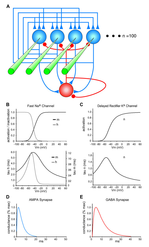
Figure 2.
Autoassociative Network Model. (A) The architecture of the 100 neuron network is illustrated with four exemplar excitatory neurons (blue). The recurrent interconnections (associational synapses) in a network with full connectivity are shown with blue triangles. Excitatory synapses are also made from each excitatory neuron onto a single interneuron that represents the total inhibition of the network (red neuron). Feedback inhibitory connections made by the interneuron onto each excitatory neuron are shown with red circles. Feedback inhibition onto the interneuron is represented using an autaptic connection. Depicted in green is the input to each neuron used to activate a neuron as part of a stimulus pattern. Each biophysically reduced model neuron had membrane properties based on a model of rhythm generation in the hippocampus [15] (see methods). (B) Voltage-gated Fast Na+ conductance steady state activation and inactivation (top) and time constants (bottom) of the m and h gating variables are shown. (C) Voltage-gated Delayed Rectifier K+ conductance steady state activation (top) and time constant (bottom) of the n gating variable is shown. (D) AMPA conductance time courses are shown. (E) GABA conductance time courses are shown.

