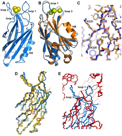
Figure 4. Crystal structure of the synaptotagmin-7 C2B domain.
(A) Ribbon diagram of the crystal structure of the synaptotagmin-7 C2B domain with the β-strands numbered from 1 to 8. The positions of helix HA and the Ca2+-binding loops are indicated. Bound Ca2+ ions are shown as yellow spheres. The N- and C-termini are labeled. (B) Superposition of ribbon diagrams of the crystal structures of synaptotagmin-7 C2B domain (blue) and the synaptotagmin-1 C2B domain [43] (PDB accession code 1UOW) (orange). The positions of α-helices HA and HB are indicated. (C) Stick models of the same superposition shown in panel (B) focusing on a region containing β-strands 4 and 5 (labeled with the corresponding numbers). Carbon atoms are colored in blue or orange for the C2B domains of synaptotagmin-7 and -1, respectively. Oxygen atoms are red and nitrogen atoms are blue in both structures. Selected side chains from the synaptotagmin-7 C2B domain are labeled. (D) Superposition of backbone stick models of the crystal structure of the synaptotagmin-7 C2B domain (blue), and the structures of the synaptotagmin-1 C2B domain determined by X-ray crystallography [43] (orange) or NMR spectroscopy [17] (PDB accession code 1K5W) (yellow). (E) Backbone stick models illustrating the extensive crystal contacts involving the Ca2+-binding loops of the synaptotagmin-7 C2B domain. The central molecule is colored in blue, with the positions of loops 1 and 3 indicated. Symmetry-related molecules within the crystal that contact the Ca2+-binding loops of this molecule are shown in red. The observed contacts are a result of crystal packing.

