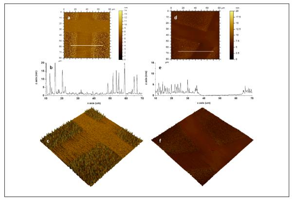
Figure 4.
AFM images of photopatterned dextran on (a, b, c) PU and (d, e, f) PS: (a, d) topography, (b, e) line scan across while line in (a, d) and (c, e) 3D topographic image of 80×80 μm2 scan size (z scale: 20 nm for PU, z scale: 15 nm for PS). A photomask is used to pattern dextran on the substrate. The unmasked regions on PU (photochemically bound dextran, DEX-PU) display dextran clusters whereas smoother regions correspond to the masked regions (“protected”, OX-PU). The unmasked regions on PS (photochemically bound dextran, DEX-PS) display a layer of dextran (1.3 ± 0.4 nm) with uniform dextran features whereas smoother regions correspond to the masked regions (“protected”, OX-PS).

