
Fig. 9.
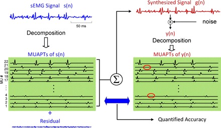
A schematic diagram of the decompose-synthesize-decompose-compare test. The sEMG signal, s(n), is decomposed, and the action potentials are used to reconstruct a synthetic signal, y(n), which in turn is decomposed. The number of motor units is identified, and the shapes and firing times of the action potentials are compared. The comparison provides a metric for the accuracy of the decomposition algorithms. (This figure is modified from one that appears in Nawab et al. 2010.)