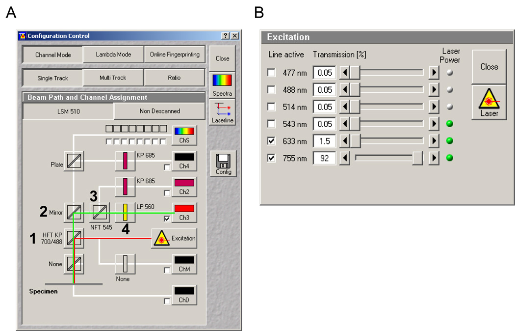
Figure 5.
Configuration Control window screen shot for Zeiss’ AIM software (version 4.2). A) Line red depicts the light path from the lasers to the PVA-coated dish, while the green line illustrates the reflected light path from the dish to the channel 3 photomultiplier tube (Ch3). Numbers show the primary dichroic (1) mirror (2) and filters (3 and 4) required for obtaining a reflected light image of the thin film surface. B) The laser excitation panel with 633nm and 755nm TP settings.

