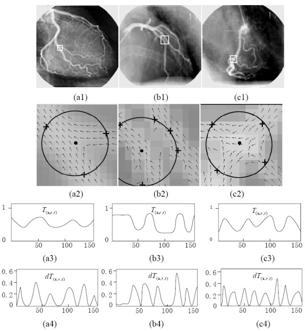
Figure 4.

Using the circular pattern detector to characterize the vessel structures, in the cases with bifurcation, paralleling, and crossing patterns. (a1)-(c1) are original images and the respective regions of interest. (a2)-(c2) are the corresponding direction maps overlaping with circular pattern detectors. (a3)-(c3) are the corresponding vessel-feature profiles on the circular template T(x,r,t). (a4)-(c4) are the corresponding magnitude profiles of the first-order derivative dT(x,r,t).
