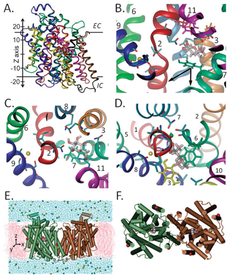
Fig. 1. The crystal structure and simulated system of vSGLT.

The whole monomer (A) or binding site region (B and C) is viewed here through the plane of the membrane (A and B) or from the external side (C). Panels C and D compare the monomeric binding site of SGLT (C), which contains the proposed Na+ ion (yellow sphere), and that of LeuT (D) with Na1 and Na2 (green and yellow spheres, respectively). All helices are colored similarly in A–C and as their equivalents in LeuT (D). Residues at the internal (green) and external hydrophobic gates in vSGLT (magenta, red and orange) and at the external gate in LeuT (green and yellow) are drawn in licorice. The simulated system (E and F), composed of the dimer embedded in a membrane bilayer (pink) and solvated in water (blue), is shown here (E, side-view and F, top view) with the α-carbons where harmonic constraints were applied (red spheres, see Methods). The arrows in (B) indicate the two directions of pulling in setups 4–11.
