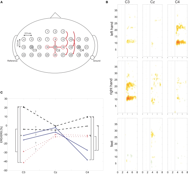
Figure 2.
(A) Schematic EEG electrode arrangement. For electrode position Cz (#17) the required electrodes for the orthogonal source derivations are highlighted. (B) Median ERD/ERS maps for C3, Cz, and C4 and for three types of motor imagery. (C) Mean ERD/ERS values of defined frequency ranges (mu and beta) and three types of motor imagery. Significant differences (p < 0.05) are marked with a square bracket, an additional asterisk indicates a significance level of p < 0.01.

