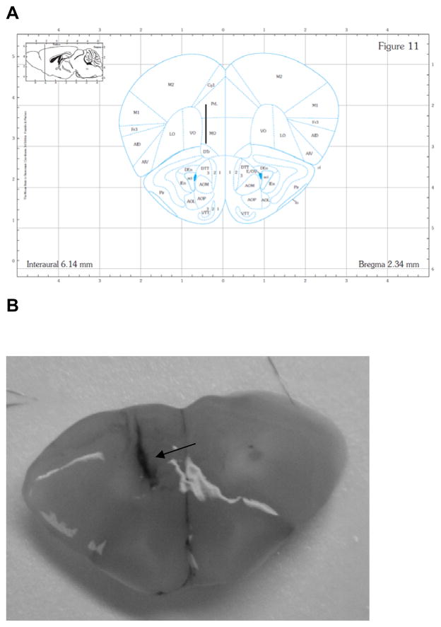
Figure 1.
Coronal sections showing microdialysis probe placement within mPFC for all animals. Panel A: the placement of the probe in mPFC. Numbers below the figure represent the position of the slice relative to bregma. The figure was adapted from Paxinos and Franklin (Paxinos and Franklin, 2001). Panel B: A picture of real brain coronal section. After each microdialysis, the brains were removed and sectioned to verify the correct position of the probe by injecting trypan blue through probe. Black arrow points out probe location.

