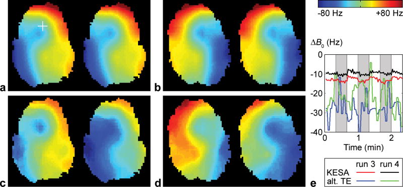
FIG. 5.
KESA B0 maps (a,b) and alternating-TE B0 maps (c,d) at two different time points of runs 3 (a,c) and 4 (b,d). e: Corresponding B0 time courses in a representative pixel (crosshair in a). The slice is the same as in Fig. 4 and the left images in b,d correspond to the same time point as in Fig. 4. The global B0 offsets determined from the automatic residual deblurring have been added to the KESA B0 maps.

