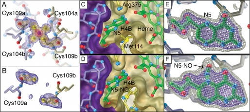
FIGURE 4.
iNOSox crystal structures before (top, PDB 3E7M) and after (bottom, PDB 3NQS) nitrosylation, showing the ZnS4 (left), dimer interface (middle), and pterin sites (right). A, in the absence of NO donor, the iNOSox ZnS4 is occupied and ordered as shown by Fo − Fc omit electron density for the zinc and its four cysteine ligands (Cys-104a, Cys-104b, Cys-109a, Cys-109b). B, after CysNO treatment during crystallization, the iNOSox ZnS4 is disrupted and residues 100 to 107 are disordered. Fo − Fc omit electron density observed for Cys-109 from each subunit indicates that the inter-atomic distance between sulfur atoms (5.7 Å) is too long for a ZnS4 cluster or disulfide bond (expected distance S-S is 2.0 Å) formation, but would accommodate two S-NO modifications. C, pterin and D, N-NO pterin (after reaction with CysNO) cofactors (green tubes with atom-colored spheres for oxygen and nitrogen atoms) both hydrogen bond with adjacent heme and are tightly packed between two iNOSox subunits (purple/gold surfaces) at the dimer interface. E, pterin and F, N-NO pterin in Fo − Fc omit electron density contoured at 3σ (blue) and 6σ (gray) are distinguishable by additional protruding electron density for the NO moiety (identified by arrow) covalently attached to position N5.

