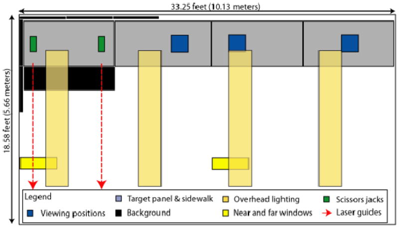
Figure 4.

Schematic diagram of the test space, showing the target panel (upper left), the sidewalk, the Black Background, the three lighting conditions (Overhead, Near Window and Far Window), and the three viewing distances (5, 10 and 20 ft). Placement of the scissor jacks under the Target Panel and the laser guides used to adjust the panel are also shown.
