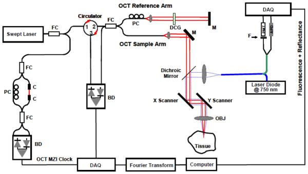
Figure 1.
Schematic of the integrated OCT/FMI system. The left side is the OCT imaging subsystem and the right side is the FMI imaging subsystem. They are combined by a dichroic mirror in the sample arm. FC: fiber coupler; PC: polarization control; C: collimator, MZI: Mach-Zehnder interferometer (frequency clocks), M: mirror, BD: balanced detector, DAQ: data acquisition board, DCG: dispersion compensating glasses, OBJ: objective; PMT: Photomultiplier Tube; APD: Avalanche Photodiode; F: Fluorescence Filter.

