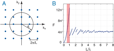
Fig. 2.
Light trapping in periodic structures. (A) Blue dots represent channels in the k space. Channels in the circle correspond to free-space propagating modes. (B) Theoretical upper limit of the absorption enhancement factor using a light-trapping scheme where a square-lattice periodic grating structure is introduced into a thin film. Red area represents a spectral range where the upper limit of the absorption enhancement factor F is above 4n2.

